A ball cage is a thin aluminium ring with a pattern of pockets that must be evenly spaced and cleanly finished — because uneven spacing loads the balls unequally and a burr scores the raceway. We build indexed radial drilling SPM for cages and round components, with servo indexing that does not accumulate error around the circle.
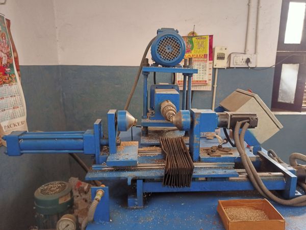
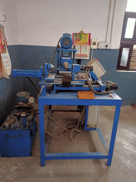
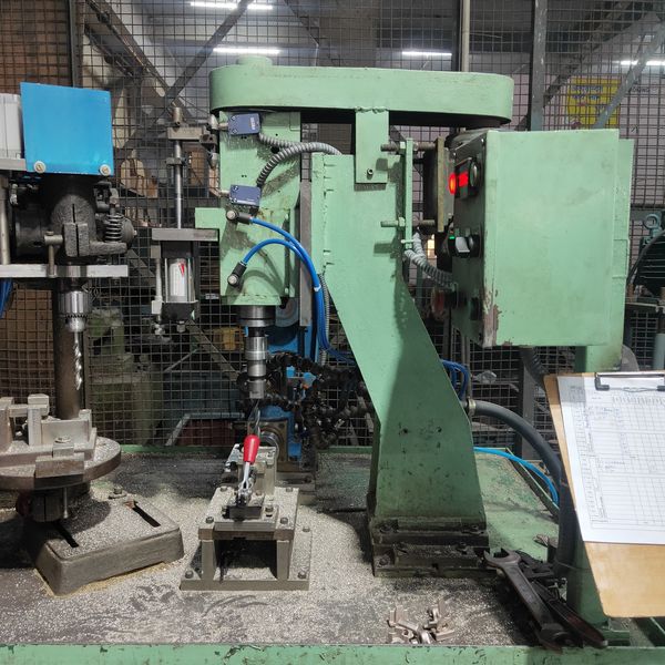
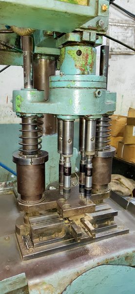
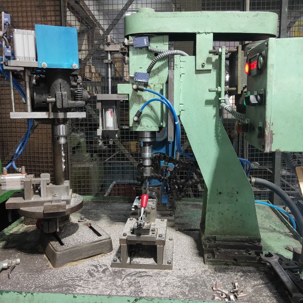
A ball cage is a thin-walled aluminium ring carrying a ring of pockets that hold the rolling elements apart in a bearing. Three things about it fight the machinist at once, and a general-purpose drilling machine loses to all three.
First, the spacing has to be genuinely equal. If one pocket sits half a degree out, the balls no longer share the load evenly and the bearing runs hot, noisy, or short. Second, the part is thin and light, so clamping hard enough to resist the cut distorts the ring — and a distorted ring machined round comes out oval when you release it. Third, aluminium burrs, and a burr left inside a pocket goes straight into the raceway.
The failure mode is cumulative error. A mechanical index that is a hundredth of a degree out per step does not matter on pocket two. By pocket twenty it is a fifth of a degree, and the last pocket does not land where the first one says it should.
The same indexed radial platform suits any round component with a pattern of holes on its circumference or its face: bearing cages and retainers, pulleys and sheaves, flanges and hubs, brake drums and discs, filter housings, distributor and manifold bodies, and rings needing bolt-hole patterns on a pitch circle.
Where the same component also needs threads, an indexed tapping station follows on the same fixture. Where the pattern is on a flat face rather than a circumference, a multi-spindle drilling machine usually gets there faster — see the drilling and tapping SPM overview for how we choose.
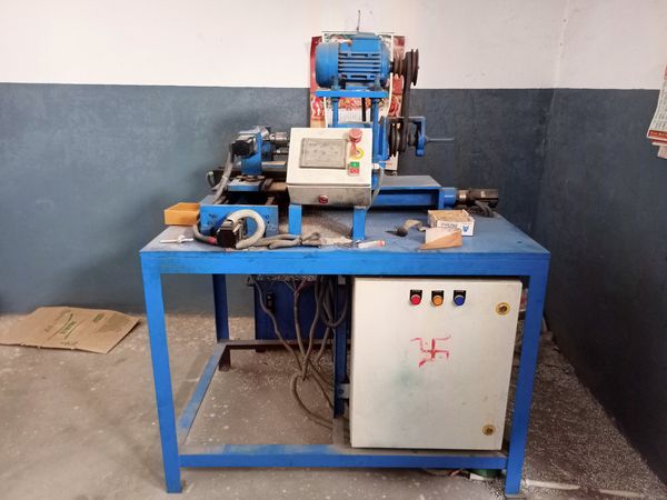
Indexing, feed, depth and pocket counting are handled by a servo drive and PLC panel built and ferruled in our own Faridabad workshop.
Each pocket commanded from an absolute datum. The twentieth is as accurate as the first, which a mechanical index cannot promise.
The PLC counts pockets and will not release the part until the full pattern is confirmed complete.
Encoder depth control, so a thin ring is not drilled through or left short when tool length changes.
Spindle load monitoring catches a blunt drill before it starts pushing burrs instead of cutting.
Pocket count, index step, diameter and depth stored per part number, with tooling ID checks.
Guarding around the cutting zone, interlocks and E-stop through a safety relay.
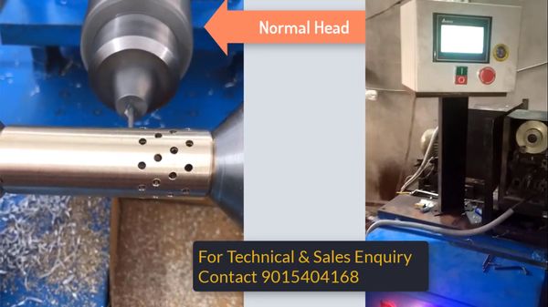
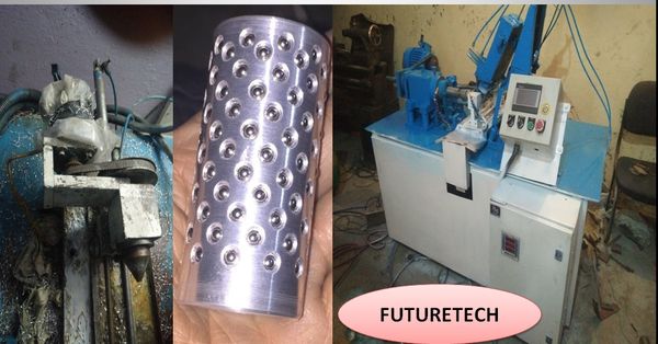
Photographs from our Faridabad workshop and from customer installations.
ball-cage-drilling-machine.jpgComplete drilling SPMball-cage-fixture.jpgIndexing fixture and clampingball-cage-component.jpgFinished aluminium cageball-cage-drill-head.jpgRadial drill headball-cage-panel.jpgPLC control panelball-cage-hmi.jpgHMI pocket count screenCage geometry drives the fixture and the indexing, and neither can be changed afterwards. Everything below is agreed before manufacturing.
| Parameter | What it covers | Fixed at |
|---|---|---|
| Cage sizes | Diameter range, wall thickness, pocket count per size | Enquiry |
| Pocket geometry | Diameter, depth, form and positional tolerance | Enquiry |
| Indexing accuracy | Required angular tolerance across the full circle | Enquiry |
| Fixture | Distributed clamping, backing support, quick-change | Drawing approval |
| Drilling | Radial or face, single or multiple heads | Drawing approval |
| Burr control | Backing support and deburr pass if specified | Drawing approval |
| Coolant | Delivery and chip evacuation from the pocket | GA approval |
| Control | Servo drive, PLC and HMI make, recipe structure | GA approval |
| Safety | Guarding, interlocks, E-stop through safety relay | Always |
At trial we run a batch and measure the angular position of every pocket on several cages — because a single good part proves nothing about cumulative error. Positional spread across the full circle, pocket diameter, depth and burr condition are all recorded against your drawing and form part of the acceptance.
Distortion is checked the same way: measured after release, not while still clamped, since a ring that is round in the fixture and oval on the bench is the classic thin-wall trap.
By commanding every pocket from an absolute datum rather than stepping from the previous position. A servo with absolute positioning does that naturally, so the last pocket is referenced to the same origin as the first and error cannot accumulate.
Distributed clamping at several points with support under the cutting zone, sized so the ring resists the cut without being deformed by the clamp. We check for distortion after release during trials, not while the part is still held.
Support behind the drill point, tooling geometry chosen for aluminium rather than borrowed from a steel job, correct speeds and feeds, and where the drawing demands it, a chamfer or deburr pass in the same cycle without re-fixturing.
Yes. Pocket count, index step, diameter and depth are stored as recipes, with quick-change fixtures per size range and a tooling ID check so the wrong fixture cannot run.
Yes. Additional stations can be added on the same indexing fixture so the part is located once and comes off finished.
The PLC counts pockets and will not release the part until the full pattern is confirmed. A part with a missing pocket cannot be unloaded as good.
Yes — Delhi NCR, Gurugram, Manesar, Bhiwadi, Ghaziabad, Noida and across India, installed and commissioned by our own engineers.
Share the drawing or a photo on WhatsApp and we will come back with a method, a cycle time and a price.
Please add a phone number or an email so we can reply.
Only a phone number or email is needed. Everything else is optional — the WhatsApp chat opens with your requirement already written, so you can add the rest there.
Want to know more, or ask anything about Ball Cage Drilling Machine? We reply fast on WhatsApp