Rotor-on-shaft assembly has to be right in two directions at once — concentric, and at exactly the correct axial position. Our rotor shaft press machines hold both, with guided rams, encoder-verified depth and a force curve that tells you whether the interference behaved the way it should.
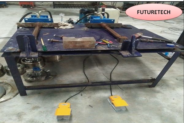
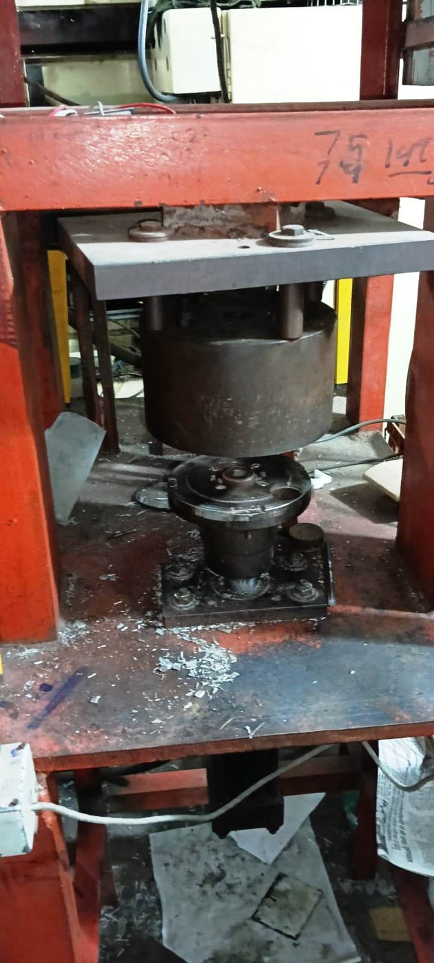
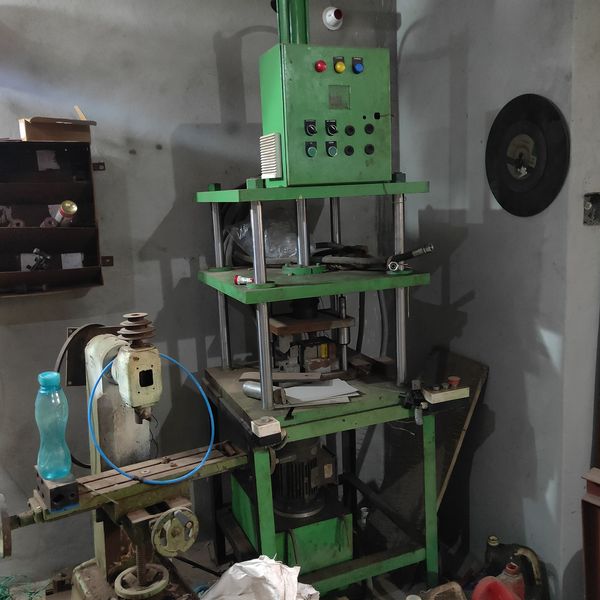
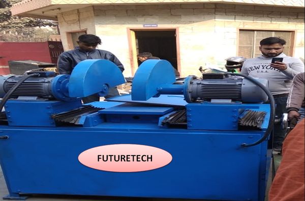
A rotor shaft press machine presses a shaft into a rotor stack, an armature, an impeller or a hub as an interference fit. Unlike most press operations, this one has two acceptance criteria that must both hold: the parts must end up concentric, and the shaft must sit at exactly the right axial position. Miss either and the assembly is scrap — and in a rotor, scrap that has already had a lot of value added to it.
Axial position is the one that catches people out. A shaft pressed a millimetre too deep changes bearing seat positions, fan and commutator location, and end float. A millimetre short and the retaining feature does not engage. Because the fit is interference, there is no second chance: once the shaft is in, taking it out damages both parts.
A mechanical stop is not depth control. Stops wear, tooling shims settle, and a stop tells you where the ram finished — not where the shaft actually sits relative to the stack. We measure the position with an encoder and verify it against the recipe before the cycle is called good.
An interference fit has a very recognisable signature. Force stays low while the shaft enters the lead-in, climbs steadily as the interference engages, and holds roughly flat through the parallel section. Departures from that shape are diagnostic in themselves — an early spike means misalignment or a burr, a force that stays low throughout means the bore or the shaft is out of tolerance and the joint will be loose in service, and a sudden collapse means something has cracked or displaced.
A loose fit is the dangerous one, because the assembly looks perfect and passes every visual check. Only the force curve shows that the interference was never really there — which is exactly the failure you do not want reaching a customer's motor.
Rotor-shaft pressing usually sits in a line with other operations we manufacture: stator into shell pressing, bearing and end shield fitting, circlip assembly, balancing preparation and leak testing of the finished housing. Built together, they share one PLC architecture and one traceability record instead of three vendors and three databases.
Driven by a hydraulic power pack built in our own workshop, or by a servo drive where positioning precision matters more than raw force — and controlled by a panel we design and ferrule ourselves.
Linear encoder verifies the seated position against the recipe. A mechanical stop alone never gets that job.
An interference that never built shows as a low, flat curve — the failure that passes every visual check but fails in service.
Where orientation matters, an indexing fixture and sensor make it impossible to press the shaft in the wrong position.
Either strategy, or force followed by position verification — chosen per part number and stored as a recipe.
Every assembly logged with its curve, final depth, operator, tooling and timestamp, exportable to your quality system.
Two-hand start or light curtain, interlocks and E-stop through a safety relay rather than a PLC output.
Photographs from our Faridabad workshop and from customer installations.
rotor-shaft-press.jpgComplete press stationrotor-shaft-fixture.jpgLocating and support toolingrotor-shaft-hmi.jpgHMI with force curve and depthrotor-shaft-tooling.jpgQuick-change tooling setrotor-shaft-panel.jpgPLC control panelrotor-shaft-installed.jpgStation on assembly lineInterference fits and axial tolerances leave nothing to interpretation. Each point below is agreed on the GA drawing before manufacturing.
| Parameter | What it covers | Fixed at |
|---|---|---|
| Press force | Peak insertion force for your largest assembly | Enquiry |
| Drive | Hydraulic or servo-electric, based on precision needed | Enquiry |
| Depth tolerance | Axial position and the tolerance band you work to | Drawing approval |
| Encoder | Resolution and mounting for position verification | Drawing approval |
| Fixture and support | Locating, squaring and reaction path through the stack | Drawing approval |
| Orientation | Keyway or flat indexing and sensing, if applicable | Drawing approval |
| Press strategy | To force, to position, or force then verify position | Trial run |
| Control and data | PLC and HMI make, recipe structure, SCADA if required | GA approval |
| Safety | Two-hand start or light curtain, interlocks, E-stop circuit | Always |
We build the envelope from a batch of your good assemblies, then run the defects you actually get — an oversize shaft, an undersize bore, a burred lead-in, a stack that was not fully supported. Each one must be caught before the station is signed off. If a real defect slips through, the criteria are wrong and we correct them at our cost, not yours.
Press to position where the axial location is critical and the interference is consistent. Press to force where the fit varies and seating matters more than exact depth. In most rotor work the right answer is force with position verified afterwards, so a shaft that reached force too early is still caught.
By taking the reaction through the stack rather than through the laminations wherever the design allows, and by supporting the pressing zone in the fixture. We work that out from your drawing before designing the tooling.
Yes, and it is one of the main reasons to monitor. A joint where the interference never built shows as a low, flat force curve — an assembly that looks perfect, passes every visual check and fails in service. A force limit alone will never see it.
Yes. Force, depth, tolerance and envelope are stored as recipes per part number, with quick-change tooling and a tooling ID check so the wrong fixture cannot be run.
Hydraulic gives high force economically and suits most rotor work. Servo gives programmable velocity, finer positioning and cleaner curves, and is worth it where the depth tolerance is tight or the cycle rate is high.
Yes. Fixture, support and press tooling are designed and made in our own workshop against your component drawing, along with the machine and the control panel.
Yes — Delhi NCR, Gurugram, Manesar, Bhiwadi, Ghaziabad, Noida and across India, installed and commissioned by our own engineers.
Share the drawing or a photo on WhatsApp and we will come back with a method, a cycle time and a price.
Please add a phone number or an email so we can reply.
Only a phone number or email is needed. Everything else is optional — the WhatsApp chat opens with your requirement already written, so you can add the rest there.
Want to know more, or ask anything about Rotor & Shaft Press Machine? We reply fast on WhatsApp