Put a plastic tank or a composite housing on a standard leak test rig and it will fail. Not because it leaks, but because it expands under pressure, the internal volume grows, and the machine reads that as a pressure drop. Testing flexible parts needs a different circuit, not a different setting.
Leak testing by pressure decay assumes one thing: that the volume inside the part stays constant. Fill it, seal it, and any pressure drop must be air escaping. That assumption holds perfectly for a cast iron housing and fails completely for a plastic tank, a fibre-reinforced duct or a moulded composite shell.
Those parts expand under pressure. The internal volume grows, and pressure falls exactly as it would if air were leaking. Nothing is escaping — the part is simply stretching. A machine tuned for metal castings reads that as a leak and rejects every good component you make, and the operators quickly learn to widen the limit until nothing fails, which defeats the purpose entirely.
Look at the curve in the animation. The steep fall after filling is the part expanding, not air escaping. Measure during that phase and every good part fails. Wait for it to stabilise, then measure, and the reading means something.
Plastic fuel and water tanks, moulded ducts and air boxes, composite and FRP housings, blow-moulded containers and bottles, plastic pump and filter housings, moulded automotive components, expansion tanks and reservoirs, and rotomoulded assemblies.
Where the same part also needs a flow check — an air box or duct, for instance — we combine both tests on one station; see air flow testing machines. And where a visual verdict is wanted alongside, a water submersion station finds the exact pinhole in a moulding.
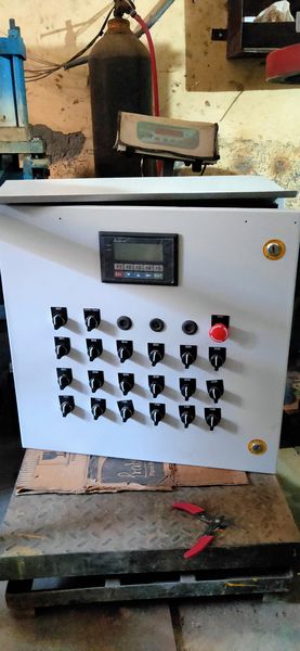
The difference is entirely in the sequence and the settle logic, which is programmed into a PLC panel built and ferruled in our own Faridabad workshop.
Measurement starts only after the part has stabilised. This one change turns a rig that rejects everything into one that works.
Distributed support and compliant seals sized for a moulded surface with draft angles, not a machined face.
A sealed master of the same material expands identically, so the expansion cancels and only real leakage remains.
Plastics move more than metals with temperature, and a part fresh off the moulding machine moves more again.
High enough to mean something, low enough not to distort the component or stress a bonded joint.
The full pressure curve logged, so a drifting mould or a material change shows up as a change in shape.
Photographs from our Faridabad workshop and from customer installations.
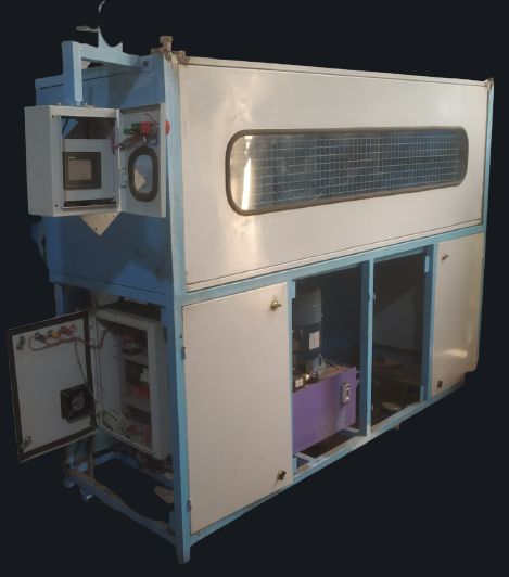
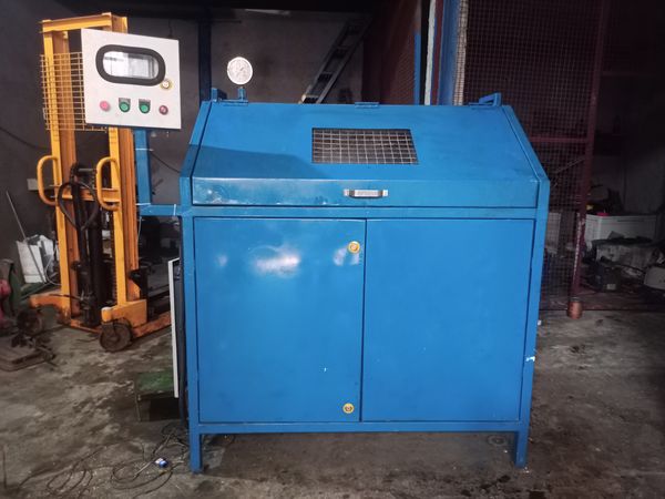
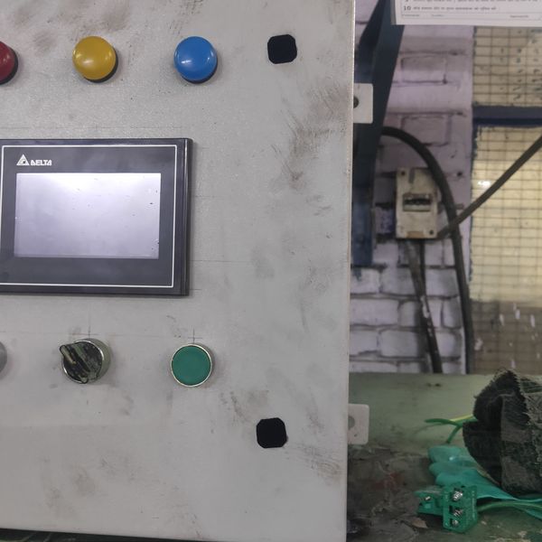
fibre-leak-test-machine.jpgComplete test stationfibre-leak-test-fixture.jpgSoft clamping fixturefibre-leak-test-hmi.jpgHMI showing settle and holdfibre-leak-test-part.jpgMoulded part under testfibre-leak-test-panel.jpgPLC control panelfibre-leak-test-master.jpgMaster part for differentialFlexible parts need their behaviour established before the rig is designed, so we ask for a sample early.
| Parameter | What it covers | Fixed at |
|---|---|---|
| Material | Plastic, composite or FRP, and its stiffness | Enquiry |
| Internal volume | Volume and expected expansion under test pressure | Enquiry |
| Test pressure | Set low enough not to distort or stress bonded joints | Trial run |
| Settle time | Established from the actual expansion behaviour | Trial run |
| Method | Absolute decay or differential against a master | Drawing approval |
| Clamping | Distributed support points and compliant sealing | Drawing approval |
| Reject limit | From your drawing, after settle behaviour is known | Trial run |
| Temperature | Compensation method and any part conditioning needed | GA approval |
| Data | Curve stored, fields logged, export format | GA approval |
For metal parts we can design a leak test rig from a drawing. For flexible parts we would rather have the component in hand, because how much it expands and how long it takes to stabilise cannot be calculated reliably — it depends on the material, the wall section, the ribbing and how the part was moulded.
So we measure it: fill a sample at candidate pressures, record the expansion curve, and find the point where it stabilises. That determines the test pressure, the settle time and whether differential testing against a master is needed. Only then do we know what the machine has to be.
Almost always because it is expanding rather than leaking. Pressure decay assumes constant internal volume. A flexible part grows under pressure, the volume increases and pressure falls, and the machine cannot tell that apart from a leak unless the sequence is designed for it.
Settle time. Let the expansion finish before measurement begins. Measuring during expansion is what makes every good part fail, and it is the first thing we correct.
A sealed known-good part of the same material and geometry is pressurised alongside yours. It expands identically, so the machine measures only the difference between the two — the expansion cancels out and what remains is real leakage. It is what makes tight limits achievable on flexible components.
Not if it is sized correctly. We set it high enough to be meaningful and low enough not to distort the part or stress bonded and welded joints, and we establish that on a sample rather than assuming.
Yes, noticeably. A warm part behaves differently as it cools. We account for it with conditioning time, temperature compensation, or differential testing against a master that has been through the same history.
Because expansion behaviour cannot be reliably calculated from a drawing. Give us a part and we will measure how much it expands and how long it takes to stabilise, which tells us what the machine actually has to be.
Yes — Delhi NCR, Gurugram, Manesar, Bhiwadi, Ghaziabad, Noida and across India, installed and commissioned by our own engineers.
Share the drawing or a photo on WhatsApp and we will come back with a method, a cycle time and a price.
Please add a phone number or an email so we can reply.
Only a phone number or email is needed. Everything else is optional — the WhatsApp chat opens with your requirement already written, so you can add the rest there.
Want to know more, or ask anything about Fibre & Moulded Item Leak Testing? We reply fast on WhatsApp